BECA 86N
Description
The BECA 86N profile is a machined virgin or filled PTFE seal ring consisting of two primary lips for dynamic sealing against the main fluid and an O-ring for static sealing. The primary sealing lips can be delivered preformed by a mandrel depending on the mounting direction.
As the sealing lip is not spring-loaded, this allows the profile to operate at higher speeds. The profile is designed with a metal cage to give stability to the joint under stress.
Advantages
Low friction coefficient; no stick-slip effect on start up
Excellent abrasion resistance
Effective in dry or poorly lubricated environments
Wide temperature range accepted
Excellent chemical inertness
Technical data
| Temperature | -30°C/+200°C |
|---|---|
| Pressure | In dynamic applications : 1.00 MPa |
| Speed | 15 m/s |
| PV maximum | PV (m/s x MPa) 7.00 in lubricated medium |
Applications
Aeronautics
Food industry
General industry
Medical
Electric motors
Motors and pumps
Robotics
Materials
Profiled seal
Virgin PTFE
Carbon filled PTFE
Graphite filled PTFE
PTFE filled with glass fibers + MOS2
Metal cage
NBR 70 Shore A
FKM 70 Shore A
EPDM 70 Shore A
HNBR 70 Shore A
VMQ 70 Shore A
Download
for use
Dimensions

Materials
| Friction ring | O'ring | Surface contact area | |||||||
|---|---|---|---|---|---|---|---|---|---|
|
Standard code |
ISO code |
Material | Color | Characteristics | Code | Type of material | Service temperature | Metal cage | |
| DP | P | Virgin PTFE | White | Chemical resistance Impermeability Dielectric Anti-stick Low friction coefficient Food industry |
K6 | NBR 70 Shore A | -30°C / +100°C |
AISI 1070-1090 AISI 304 |
Steel Stainless steel Chrome steel Aluminum Bronze Cast iron Treated surface |
| G6 | FKM 70 Shore A | -20°C / +200°C | |||||||
| C6 | EPDM 70 Shore A | -45°C / +150°C | |||||||
| F6 | VMQ 70 Shore A |
-60°C / +200°C | |||||||
| DC | C | PTFE + 25% Carbone |
Grey |
Improvement
Powerful in dynamic applications with compression |
K6 | NBR 70 Shore A | -30°C / +100°C | ||
| G6 | FKM 70 Shore A | -20°C / +200°C | |||||||
| C6 | EPDM 70 Shore A | -45°C / +150°C | |||||||
| CG | C | PTFE + 23% Carbon + 2%Graphite |
Black | K6 | NBR 70 Shore A | -30°C / +100°C | |||
| G6 | FKM 70 Shore A | -20°C / +200°C | |||||||
| C6 | EPDM 70 Shore A | -45°C / +150°C | |||||||
| DV | V | PTFE + 25 % Glass |
Blue |
Improvement
Slightly more abrasive but phenomenon corrected by the addition of MOS2 Well suited to motion applications simultaneous rotating and reciprocating |
K6 | NBR 70 Shore A | -30°C / +100°C | Steel Chrome steel Cast iron |
|
| G6 | FKM 70 Shore A | -20°C / +200°C | |||||||
| VM | M | PTFE + 15 % Glass + 5% MoS2 |
Grey | K6 | NBR 70 Shore A | -30°C / +100°C | |||
| G6 | FKM 70 Shore A | -20°C / +200°C | |||||||
| DG | G | PTFE + 15% Graphite |
Black |
Improvement
Reduced wear of metal parts Powerful in dynamic applications with self-lubrication |
K6 | NBR 70 Shore A | -30°C / +100°C | Steel Stainless steel Chrome steel Aluminum Bronze Cast iron Treated surface |
|
| G6 | FKM 70 Shore A | -20°C / +200°C | |||||||
| C6 | EPDM 70 Shore A | -45°C / +150°C | |||||||
| DB | B | PTFE + 60% Bronze |
Dark brown |
Improvement
Self-lubrication Use for dynamic seals with high compression and low wear levels |
K6 | NBR 70 Shore A | -30°C / +100°C | Steel Chrome steel Cast iron |
|
| G6 | FKM 70 Shore A | -20°C / +200°C | |||||||
| B4 | B | PTFE + 40% Bronze |
Dark brown | K6 | NBR 70 Shore A | -30°C / +100°C | |||
| G6 | FKM 70 Shore A | -20°C / +200°C | |||||||
Other qualities of materials are available depending on your particularities.
Conditions for use
Shaft design
Shaft material
Suitable materials are:
- Common steels in mechanical construction type C35 and C45
- Stainless steels type 1.4300 and 1.4112 for watertightness
- Aluminum
- Cast iron
- Plastic materials
Shaft hardness
The hardness of the shaft will depend on the linear speed (in m/s) and the level of the environment.
| HRC Hardness | Rotation speed | |||
|---|---|---|---|---|
| Environement | v ≤ 2,5 m/s | v ≤ 5,0 m/s | v ≤ 10,0 m/s | v ≤ 15,0 m/s |
| Lubricated | 35 | 40 | 52 | 58 |
| Dry | 40 | 52 | 58 | 60 |
| Water | 40 | 40 | 40 | 40 |
| Abrasive | 58 | 62 | 62 | 62 |
Surface conditions
The surface quality of the tree must take into account the recommendations below.
Standard conditions:
- Ra = 0.2 to 0.4 µm and 0.1 µm for rigorous applications
- Rz = 1.0 to 3.0 µm
Shaft tolerance
The shaft must be of tolerance h11 according to ISO 286-2
|
Shaft diameter Ød1 (mm) |
Tolerance h11 (mm) |
|---|---|
| Ød1 ≤ 3,0 | -0,060 / 0 |
| 3,0 < Ød1 ≤ 6,0 | -0,075 / 0 |
| 6,0 < Ød1 ≤ 10,0 | -0,090 / 0 |
| 10,0 < Ød1 ≤ 18,0 | -0,110 / 0 |
| 18,0 < Ød1 ≤ 30,0 | -0,130 / 0 |
| 30,0 < Ød1 ≤ 50,0 | -0,160 / 0 |
| 50,0 < Ød1 ≤ 80,0 | -0,190 / 0 |
| 80,0 < Ød1 ≤ 120,0 | -0,220 / 0 |
| 120,0 < Ød1 ≤ 180,0 | -0,250 / 0 |
| 180,0 < Ød1 ≤ 250,0 | -0,290 / 0 |
| 250,0 < Ød1 ≤ 315,0 | -0,320 / 0 |
| 315,0 < Ød1 ≤ 400,0 | -0,360 / 0 |
| 400,0 < Ød1 ≤ 500,0 | -0,400 / 0 |
Chamfer and Radius
To avoid altering the primary lip of the sealing ring during assembly, it is strongly recommended to provide a chamfer on the shaft. Please refer to the table below
|
Shaft diameter Ød1 (mm) |
Chamfer diameter |
Radius R (mm) |
|---|---|---|
| Ød1 ≤ 10,0 | Ød1 - 1,50 | 2,00 |
| 10,0 < Ød1 ≤ 20,0 | Ød1 - 2,00 | 2,00 |
| 20,0 < Ød1 ≤ 30,0 | Ød1 - 2,50 | 3,00 |
| 30,0 < Ød1 ≤ 40,0 | Ød1 - 3,00 | 3,00 |
| 40,0 < Ød1 ≤ 50,0 | Ød1 - 3,50 | 4,00 |
| 50,0 < Ød1 ≤ 70,0 | Ød1 - 4,00 | 4,00 |
| 70,0 < Ød1 ≤ 95,0 | Ød1 - 4,50 | 5,00 |
| 95,0 < Ød1 ≤ 130,0 | Ød1 - 5,50 | 6,00 |
| 130,0 < Ød1 ≤ 240,0 | Ød1 - 7,00 | 8,00 |
| 240,0 < Ød1 ≤ 500,0 | Ød1 - 11,00 | 12,00 |
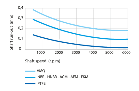
Shaft runout
Shaft runout corresponds to a deviation between the real axis of the shaft and the theoretical axis of rotation. It is important to reduce shaft runout as much as possible by positioning the seal ring as close as possible to the bearing. The table below describes the maximum permissible values depending on the rotation speed and the material of the sealing lip.
Eccentricity
The shaft and housing must be mounted centered in relation to each other to eliminate any one-sided radial loading at the sealing lip of the ring. This joint can tolerate 0.05 to 0.15 mm of coaxiality defect depending on the diameter of the shaft.
Housing design
Surface conditions
The surface quality of the accommodation must take into account the recommendations below.
Standard conditions for elastomer coated bushings:
- Ra = 0.8 µm
- Rz = 1.6 µm
Housing bore diameter tolerance
The housing bore diameter must be tolerance H8 according to ISO 286-2
| Bore diameter ØD1 (mm) |
Tolerance H8 (mm) |
|---|---|
| 3,0 < ØD1 ≤ 6,0 | 0 / +0,018 |
| 6,0 < ØD1 ≤ 10,0 | 0 / +0,022 |
| 10,0 < ØD1 ≤ 18,0 | 0 / +0,027 |
| 18,0 < ØD1 ≤ 30,0 | 0 / +0,033 |
| 30,0 < ØD1 ≤ 50,0 | 0 / +0,039 |
| 50,0 < ØD1 ≤ 80,0 | 0 / +0,046 |
| 80,0 < ØD1 ≤ 120,0 | 0 / +0,054 |
| 120,0 < ØD1 ≤ 180,0 | 0 / +0,063 |
| 180,0 < ØD1 ≤ 250,0 | 0 / +0,072 |
| 250,0 < ØD1 ≤ 315,0 | 0 / +0,081 |
| 315,0 < ØD1 ≤ 400,0 | 0 / +0,089 |
| 400,0 < ØD1 ≤ 500,0 | 0 / +0,097 |
| 500,0 < ØD1 ≤ 630,0 | 0 / +0,110 |
Housing width dimensions
The table below provides information on the recommended groove width and radius.
| Height H1 |
Width | Radius R2 max |
|
|---|---|---|---|
| L2min (H1x0,85) | L1min (H1+0,25) | ||
| 7,00 | 6,15 | 7,25 | 0,30 |
| 8,00 | 7,00 | 8,25 | |
| 10,00 | 8,70 | 10,25 | |
| 12,00 | 10,40 | 12,25 | 0,50 |
| 15,00 | 12,95 | 15,25 | |
| 20,00 | 17,20 | 20,25 | |
Radial extrusion set dimensions
When operating under pressure, and in order to prevent the seal from extruding, the seal should be held in its groove with a stop dimensioned such that the radial extrusion clearance does not exceed 0.30 mm maximum.
Assembly recommendations
Several essential rules must be respected before proceeding with the assembly of the joints:
- Check that the mechanical parts (shaft and housing) have an entry chamfer
- Deburr and chamfer or round off sharp edges, cover threaded parts
- Remove machining chips and any impurities and other foreign particles
- Thoroughly clean all mechanical parts
- When using assembly tools, check that they are clean and free of sharp edges
Only on request