BECA 006 Piston


Description
The BECA 006 Piston profile is a machined guide ring with a 30° angle cut as standard, made from filled PTFE.
Advantages
Substantial and improved lubrication conditions through the tear structures
Very good friction coefficient; no stick-slip effect
Good wear resistance; very long life
Increased absorption of foreign particles
Good vibration absorption
Technical data
| Temperature | -60°C/+200°C |
|---|---|
| Pressure | * |
| Speed | 15.0 m/s |
| Medias | Mineral hydraulic oils |
| Max. compression resistance | 30 to 35 N/mm² |
| Radial loads in dynamic applications | 15 N/mm² at 25°C |
Applications
Aerospace
Aerospace
Military
Materials
Bronze-filled PTFE
Carbon-filled PTFE
Carbon graphite-filled PTFE
Dimensions
Installation dimensions
| Bore diameter ØD1 H10 |
Groove diameter Ød1 h8 |
Groove width L1 0/+0.25 |
Extrusion gaps F/2 max |
|---|---|---|---|
| 5.97 - 37.87 | D1 - 1.63 | 3.43 | 0.18 |
| 5.97 - 37.87 | D1 - 1.63 | 6.60 | 0.18 |
| 5.97 - 37.87 | D1 - 1.63 | 9.78 | 0.18 |
| 5.97 - 37.87 | D1 - 1.63 | 12.95 | 0.18 |
| 13.97 - 113.49 | D1 - 3.20 | 3.43 | 0.23 |
| 13.97 - 113.49 | D1 - 3.20 | 6.60 | 0.23 |
| 13.97 - 113.49 | D1 - 3.20 | 9.78 | 0.23 |
| 13.97 - 113.49 | D1 - 3.20 | 12.95 | 0.23 |
| 76.02 - 266.04 | D1 - 4.78 | 3.43 | 0.28 |
| 76.02 - 266.04 | D1 - 4.78 | 6.60 | 0.28 |
| 76.02 - 266.04 | D1 - 4.78 | 9.78 | 0.28 |
| 76.02 - 266.04 | D1 - 4.78 | 12.95 | 0.28 |
Materials
| Type of material | Service temperature | Characteristics | Contact surface area |
|---|---|---|---|
| Filled PTFE | -60°C / +150°C (+200°C) | Very good friction coefficient Good wear resistance Good extrusion resistance Excellent chemical inertia |
Steel, chrome steel, Cast iron |
Design guidelines
Guide sizing
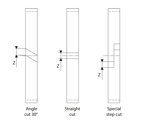
The following formulas calculate the height "H" of the wear ring in the piston or rod seal while taking the gap into account "Z" necessary at the ends of the ring after fitting. This gap "Z" offsets the thermal expansion under the effects of temperature, and prevents intermediate pressures and drag pressures in the system.
H = (F x f) / (ØD1 x Cr)
where:
H = Min. height of guide (mm)
F = Max. radial force (N)
f = Safety coefficient (we recommend 2)
ØD1 = Bore diameter (mm)
Cr = Permissible radial load in dynamic applications (N/mm²)
Types of cuts
Technical data
Surface roughness
| Roughness | Dynamic surface area | Static surface area | Groove flanks |
|---|---|---|---|
| Ra | 0.05 - 0.2 µm | ≤ 1.6 µm | ≤ 3.2 µm |
| Rz | 0.4 - 1.6 µm | ≤ 6.3 µm | ≤ 10.0 µm |
| Rmax | 0.63 - 2.5 µm | ≤ 10.0 µm | ≤ 16.0 µm |
Recommended radius of the groove diameter
| Bore diameter ØD1 |
Radius R1 max |
|---|---|
| ≤ 250.00 | 0.20 |
| > 250.00 | 0.40 |
Only on request