OVCW
Description
The OVCW profile is an inverted shaft seal composed of a single metal cage with rubber grooves on the outside of the cage and a primary sealing lip without spring.
Advantages
Very good static sealing
Very good thermal expansion compensation
Greater roughness is allowed in the fixed shaft
Reduced risk of corrosion
Easy to assemble with very limited bounce-back effect
Sealing for high viscosity fluids
Primary sealing lip generating low levels of friction and heat
Technical data
Applications
All types of rotative applications
Rotating hubs
Fixed shafts
Materials
Rubber
ACM 70 - 75 Shore A
EPDM 70 - 75 Shore A
FKM 70 - 75 Shore A
HNBR 70 - 75 Shore A
NBR 70 - 75 Shore A
Metal cage
Steel - AISI 1010
for use
Dimensions
Materials
Speed
The table below indicates the relationships between the linear speed, the rotation speed and the recommended material.
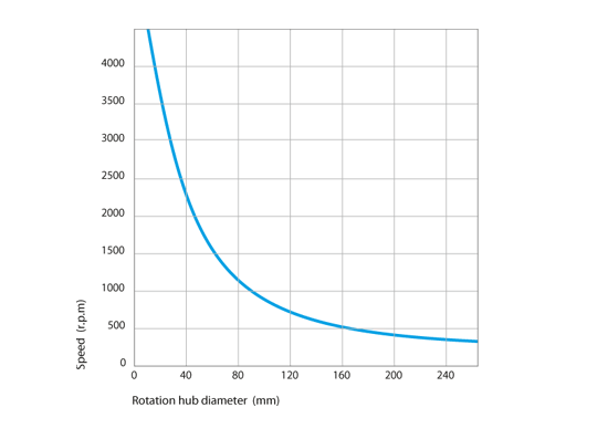
Linear speed calculation: s (m/s) = [Ø rotating hub (mm) x speed (rpm) x π] / 60,000
Pressure
The inverted shaft seals are generally used in unpressurised environments, or for pressures between 0.02 and 0.05 MPa (maximum).
Temperature
The table below indicates the temperature limits, depending on the materials and fluids used.
| Media | Maximum temperature, depending on the materials | |||||||
|---|---|---|---|---|---|---|---|---|
| ACM | AEM | EPDM | FKM | HNBR | NBR | VMQ | ||
| Mineral oils | Oils for motors | +130°C | +130°C | - | +170°C | +130°C | +100°C | +150°C |
| Oils for gearboxes | +120°C | +130°C | - | +150°C | +110°C | +80°C | +130°C | |
| Oils for hypoid gears | +120°C | +130°C | - | +150°C | +110°C | +80°C | - | |
| ATF oils | +120°C | +130°C | - | +170°C | +130°C | +100°C | - | |
| Hydraulic oils | +120°C | +130°C | +150°C | +130°C | +90°C | - | ||
| Greases | - | +130°C | - | - | +100°C | +90°C | - | |
| Fire-resistant fluids |
HFA group - Emulsion with more than 80% water | - | - | - | - | +70°C | +70°C | +60°C |
| HFB group - Opposite solution (water in oil) | - | - | - | - | +70°C | +70°C | +60°C | |
| HFC group - Polymer aqueous solution | - | - | +60°C | - | +70°C | +70°C | - | |
| HFD group - Water-free synthetic fluids | - | - | - | +150°C | - | - | - | |
| Other fluids | EL + L heating oil | - | - | - | - | +100°C | +90°C | - |
| Air | +150°C | +150°C | +150°C | +200°C | +130°C | +90°C | +200°C | |
| Water | - | - | +150°C | +100°C | +100°C | +90°C | - | |
| Water for washing | - | - | +130°C | +100°C | +100°C | +100°C | - | |
| Temperature range | Min. | -25°C | -40°C | -45°C | -20°C | -30°C | -30°C | -60°C |
| Max. | +150°C | +150°C | +150°C | +200°C | +150°C | +100°C | +200°C | |
The lip of the seal is subjected to a higher temperature due to the hub rotation, and the significant pressure and friction on the mechanical parts. Good lubrication is therefore necessary to allow for a better release of heat and thus limits the temperature rise in the parts subjected to friction.
Fluids
Greases
Greases are generally applied to bearings etc. and require specific adaptation to provide favourable operating conditions for the rotary shaft seal. To prevent the lip of the seal from sustaining more significant pressures than planned, we recommend positioning the lip seal on one side of the bearing in such a way so that the lip is not prematurely destroyed. We also recommend reducing the rotation speed by 50% when lubricated, to ensure that less heat escapes during friction.
Conditions for use
Speed
The table below indicates the relationships between the linear speed, the rotation speed and the recommended material.
Linear speed calculation: s (m/s) = [Ø rotating hub (mm) x speed (rpm) x π] / 60,000
Pressure
The inverted shaft seals are generally used in unpressurised environments, or for pressures between 0.02 and 0.05 MPa (maximum).
Temperature
The table below indicates the temperature limits, depending on the materials and fluids used.
| Media | Maximum temperature, depending on the materials | |||||||
|---|---|---|---|---|---|---|---|---|
| ACM | AEM | EPDM | FKM | HNBR | NBR | VMQ | ||
| Mineral oils | Oils for motors | +130°C | +130°C | - | +170°C | +130°C | +100°C | +150°C |
| Oils for gearboxes | +120°C | +130°C | - | +150°C | +110°C | +80°C | +130°C | |
| Oils for hypoid gears | +120°C | +130°C | - | +150°C | +110°C | +80°C | - | |
| ATF oils | +120°C | +130°C | - | +170°C | +130°C | +100°C | - | |
| Hydraulic oils | +120°C | +130°C | +150°C | +130°C | +90°C | - | ||
| Greases | - | +130°C | - | - | +100°C | +90°C | - | |
| Fire-resistant fluids |
HFA group - Emulsion with more than 80% water | - | - | - | - | +70°C | +70°C | +60°C |
| HFB group - Opposite solution (water in oil) | - | - | - | - | +70°C | +70°C | +60°C | |
| HFC group - Polymer aqueous solution | - | - | +60°C | - | +70°C | +70°C | - | |
| HFD group - Water-free synthetic fluids | - | - | - | +150°C | - | - | - | |
| Other fluids | EL + L heating oil | - | - | - | - | +100°C | +90°C | - |
| Air | +150°C | +150°C | +150°C | +200°C | +130°C | +90°C | +200°C | |
| Water | - | - | +150°C | +100°C | +100°C | +90°C | - | |
| Water for washing | - | - | +130°C | +100°C | +100°C | +100°C | - | |
| Temperature range | Min. | -25°C | -40°C | -45°C | -20°C | -30°C | -30°C | -60°C |
| Max. | +150°C | +150°C | +150°C | +200°C | +150°C | +100°C | +200°C | |
The lip of the seal is subjected to a higher temperature due to the hub rotation, and the significant pressure and friction on the mechanical parts. Good lubrication is therefore necessary to allow for a better release of heat and thus limits the temperature rise in the parts subjected to friction.
Fluids
Greases
Greases are generally applied to bearings etc. and require specific adaptation to provide favourable operating conditions for the rotary shaft seal. To prevent the lip of the seal from sustaining more significant pressures than planned, we recommend positioning the lip seal on one side of the bearing in such a way so that the lip is not prematurely destroyed. We also recommend reducing the rotation speed by 50% when lubricated, to ensure that less heat escapes during friction.
Seal design
Tolerance for the inside diameter of the seal (Ød)
The table below sets out the pre-tightening for shaft seals on the diameter of the fixed shaft.
| Shaft diameter Ød1 (mm) |
Tolerances on the inside diameter Ød of the ring | Roundness tolerance | |||
|---|---|---|---|---|---|
| Apparent metal cage | Rubber coating | Coating with grooves | Apparent metal cage | Rubber coating | |
| Ød1 ≤ 50.0 | -0.20 / -0.10 | -0.30 / -0.15 | -0.40 / -0.20 | 0.18 | 0.25 |
| 50.0 < Ød1 ≤ 80.0 | -0.23 / -0.13 | -0.35 / -0.20 | -0.45 / -0.25 | 0.25 | 0.35 |
| 80.0 < Ød1 ≤ 120.0 | -0.25 / -0.15 | -0.35 / -0.20 | -0.45 / -0.25 | 0.30 | 0.50 |
| 120.0 < Ød1 ≤ 180.0 | -0.28 / -0.18 | -0.45 / -0.25 | -0.55 / -0.30 | 0.40 | 0.65 |
| 180.0 < Ød1 ≤ 300.0 | -0.30 / -0.20 | -0.45 / -0.25 | -0.55 / -0.30 | 0.25% of ØD | 0.80 |
| 300.0 < Ød1 ≤ 500.0 | -0.35 / -0.23 | -0.55 / -0.30 | -0.65 / -0.35 | 0.25% of ØD | 1.00 |
| 500.0 < Ød1 ≤ 630.0 | -0.35 / -0.23 | -0.65 / -0.35 | -0.75 / -0.40 | - | - |
| 630.0 < Ød1 ≤ 800.0 | -0.43 / -0.28 | -0.75 / -0.40 | -0.85 / -0.45 | - | - |
Tolerance for the outside diameter of the seal (ØD)
Free and without constraint, the outside diameter of the sealing lip is always bigger than the diameter of the rotating hub. The pre-tightening or interference denotes the difference between these two values. Depending on the hub diameter, the diameter of the sealing lip is generally considered to be greater, between 0.8 and 3.5 mm.
Shaft design
Surface roughness
The recommendations below must be considered for the quality of the shaft surface area.
Standard conditions for inverted shaft seals with a rubber coating:
- Ra = 1.6 to 6.3 µm
- Rz = 10.0 to 25.0 µm
- Rmax ≤ 25.0 µm
Shaft diameter tolerance
The shaft diameter must have a tolerance of H8, in line with standard ISO 286-2
| Shaft diameter Ød1 (mm) |
Tolerance H8 (mm) |
|---|---|
| 3.0 < Ød1 ≤ 6.0 | - 0.018 / 0 |
| 6.0 < Ød1 ≤ 10.0 | -0.022 / 0 |
| 10.0 < Ød1 ≤ 18.0 | -0.027 / 0 |
| 18.0 < Ød1 ≤ 30.0 | -0.033 / 0 |
| 30.0 < Ød1 ≤ 50.0 | -0.039 / 0 |
| 50.0 < Ød1 ≤ 80.0 | -0.046 / 0 |
| 80.0 < Ød1 ≤ 120.0 | -0.054 / 0 |
| 120.0 < Ød1 ≤ 180.0 | -0.063 / 0 |
| 180.0 < Ød1 ≤ 250.0 | -0.072 / 0 |
| 250.0 < Ød1 ≤ 315.0 | - 0.081 / 0 |
| 315.0 < Ød1 ≤ 400.0 | -0.089 / 0 |
| 400.0 < Ød1 ≤ 500.0 | -0.097 / 0 |
Fixed shaft widths
The table below provides information on the width of the groove and the recommended radius.
| Height H1 (mm) |
Width | Radius R2 max (mm) |
|
|---|---|---|---|
| L2 min H1 x 0.85 |
L1 min H1 + 0.30 |
||
| 7.00 | 5.95 | 7.30 | 0.50 |
| 8.00 | 6.80 | 8.30 | |
| 10.00 | 8.50 | 10.30 | |
| 12.00 | 10.30 | 12.30 | 0.70 |
| 15.00 | 12.75 | 15.30 | |
| 20.00 | 17.00 | 20.30 | |
Housing design

Rotating hub material
Suitable materials are:
- ordinary C35 and C45 steels used in mechanical construction
- 1.4300 and 1.4112 stainless steels for sealing water
- sprayed carbide coatings
- graphite
- malleable cast iron
- materials with a CVD and PVD coating
Not appropriate:
- hard chrome coatings due to irregular wear
- plastic materials resulting from low thermal conductivity, which can lead to a disturbance in the transport of heat, an increase in temperature in friction areas with the shaft seal, as well as a potential softening
Rotating hub hardness
The hardness of the rotating hub will depend on the linear speed (in m/s) and the level of pollution.
| Rotation speed | Hardness in HRC |
|---|---|
| s ≤ 4 m/s | 45 HRC |
| 4.0 < s ≤ 10.0 m/s | 55 HRC |
| s > 10.0 m/s | 60 HRC |
Surface roughness
The recommendations below must be considered for the quality of the housing surface area.
Standard conditions:
- Ra = 0.2 to 0.8 µm and 0.1 for demanding applications
- Rz = 1.0 to 4.0 µm
- Rmax ≤ 6.3 µm
Rotating hub tolerance
The hub must have a tolerance of H11, in line with standard ISO 286-2
| Rotating hub diameter ØD1 (mm) |
Tolerance H11 (mm) |
|---|---|
| 3.0 < ØD1 ≤ 6.0 | 0 / +0.075 |
| 6.0 < ØD1 ≤ 10.0 | 0 / +0.090 |
| 10.0 < ØD1 ≤ 18.0 | 0 / +0.110 |
| 18.0 < ØD1 ≤ 30.0 | 0 / +0.130 |
| 30.0 < ØD1 ≤ 50.0 | 0 / +0.160 |
| 50.0 < ØD1 ≤ 80.0 | 0 / +0.190 |
| 80.0 < ØD1 ≤ 120.0 | 0 / +0.220 |
| 120.0 < ØD1 ≤ 180.0 | 0 / +0.250 |
| 180.0 < ØD1 ≤ 250.0 | 0 / +0.290 |
| 250.0 < ØD1 ≤ 315.0 | 0 / +0.320 |
| 315.0 < ØD1 ≤ 400.0 | 0 / +0.360 |
| 400.0 < ØD1 ≤ 500.0 | 0 / +0.400 |
| 500.0 < ØD1 ≤ 630.0 | 0 / +0.440 |
Chamfer and radius
You are strongly advised to install a chamfer on the hub so as not to alter the primary sealing sealing lip of the shaft seal during assembly. Please refer to the table below.
| Rotating hub diameter ØD1 (mm) |
Chamfer diameter ØD3 (mm) |
Radius R (mm) |
|---|---|---|
| ØD1 ≤ 10.0 | ØD1 + 1.50 | 2.00 |
| 10.0 < ØD1 ≤ 20.0 | ØD1 + 2.00 | 2.00 |
| 20.0 < ØD1 ≤ 30.0 | ØD1 + 2.50 | 3.00 |
| 30.0 < ØD1 ≤ 40.0 | ØD1 + 3.00 | 3.00 |
| 40.0 < ØD1 ≤ 50.0 | ØD1 + 3.50 | 4.00 |
| 50.0 < ØD1 ≤ 70.0 | ØD1 + 4.00 | 4.00 |
| 70.0 < ØD1 ≤ 95.0 | ØD1 + 4.50 | 5.00 |
| 95.0 < ØD1 ≤ 130.0 | ØD1 + 5.50 | 6.00 |
| 130.0 < ØD1 ≤ 240.0 | ØD1 + 7.00 | 8.00 |
| 240.0 < ØD1 ≤ 500.0 | ØD1 + 11.00 | 12.00 |
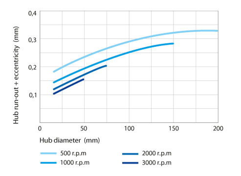
Rotating support run out and eccentricity
The hub run out represents a deviation between the current axis of the rotating hub and the theoretical rotation axis. It is important to reduce the hub run out as much as possible by positioning the shaft seal as close as possible to the bearing.
The fixed shaft and rotating hub must be assembled centred on one another in order to remove any unilateral radial load at the sealing lip of the ring.
The table below sets out the maximum permissible values depending on the rotation speed and the diameter of the rotating hub.
Rotating hub machining
Correct machining of the rotating hub is essential to the proper operation of the sealing system.
- Plunge grinding: preferred machining method to ensure the absence of striations on the hub (0 +/- 0.05°)
- Turning: suitable for shafts used with a unidirectional sense of rotation
Machining guidelines for surface adjustments
| Parameters | Requirements |
|---|---|
| Speed of the part to be machined | 30 to 300 rpm |
| Wheel speed | 1500 to 1700 rpm |
| Surfacing feed | < 0.02 mm/turn |
| Dressing tool | multi-grain dressing diamond, single drain dressing diamond |
| Grinding rate feed | approximately 0.02 mm |
| Spark duration | full spark, 30 secs min. |
| Passing depth | > Rmax of the old machining operation |
| Eccentricity of the tool and part to be machined | the best possible |
Only on request