UAO3


Description
The UAO3 profile is an inverted cassette seal, where the upper part is fitted on the rotating hub. The lower part is fitted onto the fixed shaft and is composed of a primary sealing lip with an integrated spring and an anti-pollution sealing lip. A metal reinforcement is built in to offer additional protection in the dynamic sealing area when faced with a moderate pollution level.
Advantages
Low friction coefficient
Standard protection against dirt
Reduced need for maintenance
Easy to fit with low risk of seal deterioration
Technical data
| Temperature | < 120°C |
|---|---|
| Pressure | 0.05 MPa |
| Speed | 10 m/s |
| Level of pollution | Moderate |
Applications
Axles
Pinions
Hubs
Construction
Agriculture
Commercial vehicles
Materials
Rubber
ACM 70 - 75 Shore A
FKM 70 - 75 Shore A
HNBR 70 - 75 Shore A
NBR 70 - 75 Shore A
Metal cage
Steel - AISI 1010
Stainless steel - AISI 304
Stainless steel - AISI 316
Spring
Steel - AISI 1070 - 1090
Stainless steel - AISI 316
for use
Dimensions
Materials
Metal cage - Spring
The table below shows the materials that we can offer for metal cages and springs.
| Application | Material | Standard | Characteristics |
|---|---|---|---|
| Metal cage | Non-alloy standard steel | AISI 1010 (DIN 1624) |
Cold rolled steel |
| Metal cage | Nickel chrome steel | AISI 304 (DIN 1.4301 - V2A) |
Standard stainless steel |
| Metal cage and spring | Chrome-nickel-molybdenum steel | AISI 316 (DIN 1.4401 - V4A) |
Stainless steel highly resistant to corrosion |
| Spring | Steel for springs | AISI 1070 - 1090 DIN 17223 |
Cold drawn carbon steel wire |
| Spring | Nickel chrome steel | AISI 302 (DIN 1.4300) |
Stainless steel for springs with a high carbon content |
Rubbers
ACM (Polyacrylate)
Polymers containing ethyl acrylate (or butyl acrylate) have a small amount of monomer, which is necessary for cross-linking; ACM is a material with better heat resistance than NBR. It is often used for automatic gearboxes.
| Chemical resistance | Mineral oils (motor oils, gear box oils, ATF oils) Atmospheric and ozone agents |
|---|---|
| Compatibility issue | Glycol-based brake fluids (Dot 3 & 4) Aromatic and chlorinated hydrocarbons Water and steam Acids, alkalis and amines |
| Temperature range | -25°C to + 150°C (short-term peak at +160°C) -35°C / +150°C with particular ACMs |
FKM (fluorinated rubber)
Depending on their structure and fluorine content, the chemical resistance and resistance to the cold in fluororubbers can vary. This FKM-based rubber is very often used for high-temperature hydraulics and pneumatics, for industrial valves, injection/fuel systems, motor seals and high-vacuum systems.
| Chemical resistance | Mineral oils and greases, ASTM n°1, IRM 902 and IRM 903 oils. Fire-resistant liquids (HFD) Silicone oils and greases Mineral and vegetable oils and greases Aliphatic hydrocarbons (propane, butane, petroleum) Aromatic hydrocarbons (benzene, toluene) Chlorinated hydrocarbons (trichlorethylene) Fuel (including high alcohol content) Atmospheric and ozone agents |
|---|---|
| Compatibility issue | Glycol-based brake fluids Ammonia gas Organic acids with a low molecular weight (formic and acetic acids) |
| Temperature range | -20°C / +200°C (short-term peak at +230°C) -40°C / +200°C with particular FKMs |
HNBR (Hydrogenated Nitrile Butadiene Rubber)
This HNBR-based rubber is obtained through selective hydrogenation of the NBR's butadiene groups. It is commonly used for power-assisted steering and for air conditioning.
| Chemical resistance | Aliphatic hydrocarbons Mineral and vegetable oils and greases Fire-resistant fluids (HFA, HFB and HFC) Diluted acids, saline solutions and bases for operation at an average temperature Water and steam up to +150°C Atmospheric and ozone agents |
|---|---|
| Compatibility issue | Chlorinated hydrocarbons Polar solvents (ketones, esters and ethers) Strong acids |
| Temperature range | -30°C / +150°C (short-term peak at +160°C) -40°C / +150°C with particular HNBRs |
NBR (Nitrile Butadiene Rubber)
Nitrile rubber (NBR) is the general term for acrylonitrile-butadiene copolymer. The ACN content can vary between 18% and 50%. While the acrylonitrile content is important, the resistance to oil and fuel is more so. Conversely, the elasticity and compression set are not as good. The NBR has good mechanical properties and good wear resistance. However, its resistance to atmospheric agents and the ozone is relatively low.
| Chemical resistance | Aliphatic hydrocarbons (propane, butane, petroleum, diesel fuel) Mineral oils and greases Fire-resistant fluids (HFA, HFB and HFC) Diluted acids, low-temperature alkaline and saline solutions Water (up to +100°C max) |
|---|---|
| Compatibility issue | Fuels with high aromatic content Aromatic hydrocarbons (benzene) Chlorinated hydrocarbons (trichlorethylene) Polar solvents (ketone, acetone, acetic acid, ethylene-ester) Strong acids Glycol-based brake fluids Atmospheric and ozone agents |
| Temperature range | -30°C / +100°C (short-term peak at +120°C) -40°C / +100°C with particular NBRs |
The table below gives an overview of the physical, chemical and mechanical characteristics for each of the materials.
| Characteristics/Materials | ACM | FKM | HNBR | NBR |
|---|---|---|---|---|
| Abrasion resistant | 2 | 2 | 2 | 2 |
| Resistance to acids | 4 | 1 | 1 | 3 |
| Chemical resistance | 4 | 1 | 2 | 2 |
| Resistance to cold | 4 | 4 | 2 | 2 |
| Dynamic properties | 3 | 2 | 1 | 2 |
| Electrical properties | 3 | 4 | 3 | 3 |
| Flame resistant | 4 | 1 | 4 | 4 |
| Heat resistant | 1 | 1 | 1 | 2 |
| Sealing water | 1 | 2 | 2 | 2 |
| Oil resistant | 1 | 1 | 1 | 1 |
| Ozone resistant | 1 | 1 | 2 | 4 |
| Tearing resistant | 2 | 3 | 2 | 2 |
| Traction resistant | 3 | 1 | 1 | 2 |
| Water/vapour resistant | 4 | 3 | 1 | 2 |
| Resistance to atmospheric agents | 1 | 1 | 2 | 3 |
1. Excellent properties 2. Good properties 3. Average properties 4. Poor properties
Chemical compatibility
A "Chemical compatibility guide" catalogue can be downloaded from the Documentation section. You can also use our online "Chemical compatibility" tool free of charge.
These two tools give you the option of measuring the behaviour of our materials that come into contact with the majority of existing fluids. The data displayed is the result of rigorous testing of the ambient temperature and in consultation with previous publications. Test results are not fully representative due to the specific features of your application. The tests performed actually do not consider additives and impurities that may exist under the actual conditions of use, nor the potential elevation of temperatures. Other parameters can also alter the behaviour of our materials, such as the hardness, persistence, abrasion, etc. We therefore recommend performing your own tests to verify the compatibility of our materials according to your specific application. Our technical team can provide you with any additional information.
Conditions for use
Technical data
| Technical data | NBR 75 Shore A | FKM 75 Shore A | ACM 75 Shore A | HNBR 75 Shore A |
|---|---|---|---|---|
| Temperature | -30°C/+80°C | -20°C/+120°C | -25°C/+100°C | -30°C/+100°C |
| Speed | 8 m/s | 10 m/s | 9 m/s | 9 m/s |
| Pressure | 0.02 - 0.05 MPa | 0.02 - 0.05 MPa | 0.02 - 0.05 MPa | 0.02 - 0.05 MPa |
| Level of pollution | Moderate | Moderate | Moderate | Moderate |
Linear speed calculation:
s (m/s) = [Ø rotating support (mm) x speed (rpm) x π] / 60,000
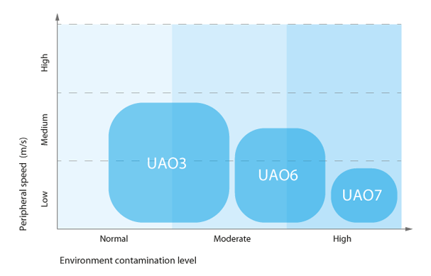
The graph below compares the different cassette seal profiles according to their permissible speed and their capacity to resist different levels of pollution.
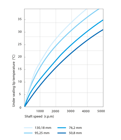
Temperature elevation
The sealing lips of the cassette seal are subjected to a higher temperature due to the rotation of the sleeve fitted on the rotating hub, and the greater friction on the inside of the seal. Good lubrication is therefore necessary to allow for a better release of heat and thus limits the temperature rise in the parts subjected to friction.
By definition, the temperature at the edge of the seal is High when the rotation speed (and thus the linear speed) as well as the shaft diameter increases.
Fluids
Mineral oils
In general, this type of oil has few additives and is therefore perfectly suitable for all of the rubbers used for the rotary shaft seals. The following oils are suitable for revolving applications:
- motor oils
- gearbox oils
- hypoid oils
- ATF oils for automatic gearboxes
- transmission oils
synthetic oils
This type of oil is used to improve different characteristics such as the resistance to ageing, resistance to high temperatures, viscosity, etc. and has a good compatibility with the majority of rubbers used for the seals for the rotary shaft. Tests may need to be performed beforehand to measure the degree of compatibility of this type of oil with the materials used. Among the synthetic oils are:
- brake fluids
- fluids for automatic gearboxes
- fluids for suspensions
- fluids for steering systems
- fluids for hydraulic transmissions
Hypoid oils
This type of oil contains special components such as EP additives. These enable lubrication and thus limit any seizing at the bearings, for example. When affected by heat, these additives have the tendency to lead to deposits on the sealing lip. That is why we recommend using seals for the rotating shaft with a sealing lip comprising return pumping leads in order to limit the increase in temperature and above all, to reduce these potential carbon deposits.
Greases
Greases are generally applied to bearings etc. and require specific adaptation to provide favourable operating conditions for the rotary shaft seal. To prevent the lip of the seal from sustaining more significant pressures than planned, we recommend positioning the lip seal on one side of the bearing in such a way so that the lip is not prematurely destroyed. We also recommend reducing the rotation speed by 50% when lubricated, to ensure that less heat escapes during friction.
Aggressive fluids
It is critical to choose the correct material to better resist different aggressive fluids (acids, solvents, chemical products, etc.). For applications in a rotating environment, we recommend using materials such as FKM rather than NBR. We can develop custom-made PTFE-based cassette seals for operations that are dry or use very little lubrication, and where the rubbers do not resist certain aggressive fluids.
Seal design
Tolerance for the outside diameter of the seal (ØD)
The table below indicates the pre-tightening for shaft seals on the diameter of the rotating hub according to standard ISO 6194-1. For specific cases, we may modify characteristics associated with the dimensions and tolerances, depending on the customer's needs or the final application.
| ØD1 rotating hub | Tolerances on the outside diameter ØD of the ring | ||
|---|---|---|---|
| Apparent metal cage | Rubber coating | Coating with grooves | |
| ØD1 ≤ 50.0 | + 0.10 / + 0.20 | + 0.15 / + 0.30 | + 0.20 / + 0.40 |
| 50.0 < ØD1 ≤ 80.0 | + 0.13 / + 0.23 | + 0.20 / + 0.35 | +0.25 / + 0.45 |
| 80.0 < ØD1 ≤ 120.0 | + 0.15 / + 0.25 | + 0.20 / + 0.35 | + 0.25 / + 0.45 |
| 120.0 < ØD1 ≤ 180.0 | + 0.18 / + 0.28 | + 0.25 / + 0.45 | + 0.30 / + 0.55 |
| 180.0 < ØD1 ≤ 300.0 | + 0.20 / + 0.30 | + 025 / + 0.45 | + 0.30 / + 0.55 |
| 300.0 < ØD1 ≤ 500.0 | + 0.23 / + 0.35 | + 0.30 / + 0.55 | + 0.35 / + 0.65 |
| 500.0 < ØD1 ≤ 630.0 | + 0.23 / + 0.35 | + 0.35 / + 0.65 | + 0.40 / + 0.75 |
| 630.0 < ØD1 ≤ 800.0 | + 0.28 / + 0.43 | + 0.40 / + 0.75 | + 0.45 / + 0.85 |
Tolerance for the inside diameter of the seal (Ød)
The table below sets out the pre-tightening for shaft seals on the fixed shaft. For specific cases, we may modify characteristics associated with the dimensions and tolerances, depending on the customer's needs or the final application.
| Ød1 fixed shaft | Tolerances on the inside diameter Ød of the ring | ||
|---|---|---|---|
| Apparent metal cage | Rubber coating | Coating with grooves | |
| Ød1 ≤ 50.0 | - 0.10 / - 0.20 | - 0.15 / - 0.30 | - 0.20 / - 0.40 |
| 50.0 < Ød1 ≤ 80.0 | - 0.13 / - 0.23 | - 0.20 / - 0.35 | - 0.25 / - 0.45 |
| 80.0 < Ød1 ≤ 120.0 | - 0.15 / - 0.25 | - 0.20 / - 0.35 | - 0.25 / - 0.45 |
| 120.0 < Ød1 ≤ 180.0 | - 0.18 / - 0.28 | - 0.25 / - 0.45 | - 0.30 / - 0.55 |
| 180.0 < Ød1 ≤ 300.0 | - 0.20 / - 0.30 | - 025 / - 0.45 | - 0.30 / - 0.55 |
| 300.0 < Ød1 ≤ 500.0 | - 0.23 / - 0.35 | - 0.30 / - 0.55 | - 0.35 / - 0.65 |
| 500.0 < Ød1 ≤ 630.0 | - 0.23 / - 0.35 | - 0.35 / - 0.65 | - 0.40 / - 0.75 |
| 630.0 < Ød1 ≤ 800.0 | - 0.28 / - 0.43 | - 0.40 / - 0.75 | - 0.45 / - 0.85 |
Roundness tolerance
| ØD1 rotating hub | Roundness tolerance | |
|---|---|---|
| Apparent metal cage | Rubber coating | |
| ØD1 ≤ 50.0 | 0.18 | 0.25 |
| 50.0 < ØD1 ≤ 80.0 | 0.25 | 0.35 |
| 80.0 < ØD1 ≤ 120.0 | 0.30 | 0.50 |
| 120.0 < ØD1 ≤ 180.0 | 0.40 | 0.65 |
| 180.0 < ØD1 ≤ 300.0 | 0.25% of the outside diameter | 0.80 |
| 300.0 < ØD1 ≤ 500.0 | 0.25% of the outside diameter | 1.00 |
| 500.0 < ØD1 ≤ 630.0 | - | - |
| 630.0 < ØD1 ≤ 800.0 | - | - |
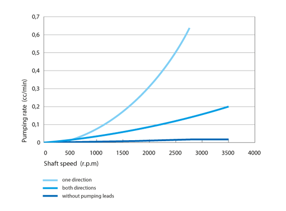
Pumping leads
To maintain the lubrication, we recommend integrating diagonal pumping leads on the primary sealing lip, on the air side oriented in the direction of the sleeve rotation, which reinforces the pumping effect of the rubber's micro-striations. Below are the types of return pumping leads that can be made:
The graph below sets out the pumping level of the rubber's micro-striations:
Shaft design
Surface roughness
The recommendations below must be considered for the quality of the fixed shaft surface area.
- Ra = 0.8 to 3.2 µm
- Rmax = 10.0 to 16.0 µm
Tolerance of the fixed shaft diameter
The shaft diameter must have a tolerance of h8, in line with standard ISO 286-2.
| Ød1 fixed shaft (mm) | h8 tolerance (mm) |
|---|---|
| Ød1 ≤ 3.0 | -0.014 / 0 |
| 3.0 < Ød1 ≤ 6.0 | -0.018 / 0 |
| 6.0 < Ød1 ≤ 10.0 | -0.022 / 0 |
| 10.0 < Ød1 ≤ 18.0 | -0.027 / 0 |
| 18.0 < Ød1 ≤ 30.0 | -0.033 / 0 |
| 30.0 < Ød1 ≤ 50.0 | -0.039 / 0 |
| 50.0 < Ød1 ≤ 80.0 | -0.046 / 0 |
| 80.0 < Ød1 ≤ 120.0 | -0.054 / 0 |
| 120.0 < Ød1 ≤ 180.0 | -0.063 / 0 |
| 180.0 < Ød1 ≤ 250.0 | -0.072 / 0 |
| 250.0 < Ød1 ≤ 315.0 | -0.081 / 0 |
| 315.0 < Ød1 ≤ 400.0 | -0.089 / 0 |
| 400.0 < Ød1 ≤ 500.0 | -0.097 / 0 |
Chamfer and radius
We urge you to fit a chamfer on the fixed shaft. We recommend opting for:
20° (+/-5°) x 2 mm
Housing design
Rotating hub material
Suitable materials are:
- ordinary C35 and C45 steels used in mechanical construction
- 1.4300 and 1.4112 stainless steels for sealing water
- sprayed carbide coatings
- graphite
- malleable Cast iron
- materials with a CVD and PVD coating
Not appropriate:
- hard chrome coatings due to irregular wear
- plastic materials resulting from low thermal conductivity, which can lead to a disturbance in the transport of heat, an increase in temperature in friction areas with the shaft seal, as well as a potential softening
Rotating hub hardness
The hardness of the rotating hub will depend on the linear speed (in m/s) and the level of pollution.
| Rotation speed | Hardness in HRC |
|---|---|
| ≤ 4 m/s | 45 HRC |
| 4.0 < s ≤ 10.0 m/s | 55 HRC |
| s > 10.0 m/s | 60 HRC |
Surface roughness
The quality of the rotating hub surface area must take the recommendations below into account.
- Ra = 0.8 to 3.2 µm
- Rmax = 10.0 to 16.0 µm
Rotating hub tolerance
The rotating hub must have a tolerance of H8, in line with standard ISO 286-2. For specific and aggressive applications, we recommend a tolerance of H7.
| ØD1 rotating hub | H8 tolerance (mm) |
|---|---|
| 3.0 < ØD1 ≤ 6.0 | 0 / +0.018 |
| 6.0 < ØD1 ≤ 10.0 | 0 / +0.022 |
| 10.0 < ØD1 ≤ 18.0 | 0 / +0.027 |
| 18.0 < ØD1 ≤ 30.0 | 0 / +0.033 |
| 30.0 < ØD1 ≤ 50.0 | 0 / +0.039 |
| 50.0 < ØD1 ≤ 80.0 | 0 / +0.046 |
| 80.0 < ØD1 ≤ 120.0 | 0 / +0.054 |
| 120.0 < ØD1 ≤ 180.0 | 0 / +0.063 |
| 180.0 < ØD1 ≤ 250.0 | 0 / +0.072 |
| 250.0 < ØD1 ≤ 315.0 | 0 / +0.081 |
| 315.0 < ØD1 ≤ 400.0 | 0 / +0.089 |
| 400.0 < ØD1 ≤ 500.0 | 0 / +0.097 |
| 500.0 < ØD1 ≤ 630.0 | 0 / +0.110 |
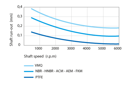
Run out
The run out reflects a deviation between the current axis and the theoretical rotation axis. It is important to reduce the run out as much as possible by positioning the cassette seal as close as possible to the bearing. The table below sets out the maximum permissible values depending on the rotation speed and the sealing lip material.
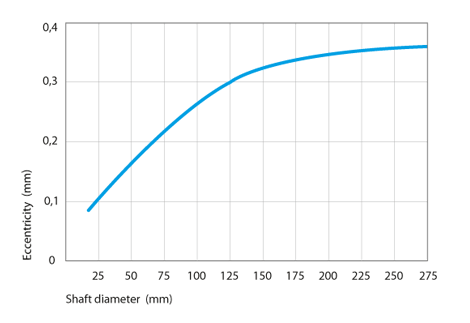
Eccentricity
The shaft and rotating hub must be assembled centred on one another in order to remove any unilateral radial load at the sealing lip.
Axial movement
The cassette seals can tolerate axial movements greater than +/- 0.1 mm. However, this can lead to premature wear in the system.
Chamfer and radius
You are strongly advised to install a chamfer on the rotating hub so as not to alter the primary sealing lip of the cassette seal during assembly. We recommend opting for:
20° (+/-5°) x 2 mm
|
UAO3 85x140x17
|
85,00 | 140,00 | 17,00 |
|
UAO3 90x130x17
|
90,00 | 130,00 | 17,00 |
|
UAO3 100x130x17
|
100,00 | 130,00 | 17,00 |
|
UAO3 100x140x17
|
100,00 | 140,00 | 17,00 |
|
UAO3 110x140x17
|
110,00 | 140,00 | 17,00 |
|
UAO3 111x146x17
|
111,00 | 146,00 | 17,00 |
|
UAO3 120x160x17
|
120,00 | 160,00 | 17,00 |
|
UAO3 125x160x17
|
125,00 | 160,00 | 17,00 |
|
UAO3 128x164x17
|
128,00 | 164,00 | 17,00 |
|
UAO3 130x160x17
|
130,00 | 160,00 | 17,00 |
|
UAO3 130x170x17
|
130,00 | 170,00 | 17,00 |
|
UAO3 135x165x17
|
135,00 | 165,00 | 17,00 |
|
UAO3 140x170x17
|
140,00 | 170,00 | 17,00 |
|
UAO3 145x175x17
|
145,00 | 175,00 | 17,00 |
|
UAO3 150x180x17
|
150,00 | 180,00 | 17,00 |
|
UAO3 155x190x17
|
155,00 | 190,00 | 17,00 |
|
UAO3 160x196x17
|
160,00 | 196,00 | 17,00 |
|
UAO3 178x205x17
|
178,00 | 205,00 | 17,00 |
|
UAO3 187x230x17
|
187,00 | 230,00 | 17,00 |
|
UAO3 190x230x17
|
190,00 | 230,00 | 17,00 |
|
UAO3 320x360x19
|
320,00 | 360,00 | 19,00 |