BECA 010 FEP
Description
The BECA 010 FEP profile is a rubber O'Ring, a circular ring with a round cross-section, wrapped in a FEP impermeable sheath (fluorinated ethylene propylene). Unlike PTFE O'Rings, FEP O'Rings retain their elastic properties, as with standard O'Rings, and have a great chemical resistance thanks to the FEP envelope.
Advantages
Wide temperature range
Excellent chemical resistance
Low friction coefficient; no stick-slip effect
Technical data
| Temperature | FKM base: -20°C / +200°C |
|---|---|
| Pressure | Up to 25 MPa (combined with a BECA 008 back-up ring from 5 MPa) |
| Speed | 0 m/s, static applications only |
| Medias | The majority of liquid, gaseous and chemical substances |
Applications
Food & beverage
Chemical
Cosmetic
Medical
Petrochemical
Pharmaceutical
Water treatment
Materials
FKM with FEP envelope
VMQ with FEP envelope
Dimensions
Materials
FEP sheath
The FEP (tetrafluoroethylene - hexafluoropropylene) sheath is a material that has same mechanical properties as PTFE (polytetrafluoroethylene). It has an excellent chemical inertia and good abrasion resistance.
FKM-FEP
Depending on their structure and fluorine content, fluoroelastomers can vary in terms of chemical resistance and resistance to cold. This FKM-based rubber is very often used for high-temperature hydraulic and pneumatic systems, industrial valves, injection/fuel systems, motor seals and high-vacuum systems.
| Chemical resistance | Mineral oils and greases, ASTM n°1, IRM 902 and IRM 903 oils. Fire-resistant liquids (HFD) Silicone oils and greases Mineral and vegetable oils and greases Aliphatic hydrocarbons (propane, butane, petroleum) Aromatic hydrocarbons (benzene, toluene) Chlorinated hydrocarbons (trichlorethylene) Petrol (including high alcohol content) Atmospheric and ozone agents |
|---|---|
| Compatibility issue | Glycol-based brake fluids Ammoniac gas Organic acids with a low molecular weight (formic and acetic acids) |
| Temperature range | -20°C / +200°C -40°C / +200°C with special FKMs |
VMQ-FEP
This FVMQ-based rubber is very often used for fuel systems.
| Chemical resistance | Animal and vegetable oils and greases Moderate water temperature Diluted saline solutions Atmospheric and ozone agents |
|---|---|
| Compatibility issue | Superheated steam up to +120°C Chlorinated hydrocarbons with a low molecular weight (trichlorethylene) Aromatic hydrocarbons (benzene, toluene) |
| Temperature range | -60°C / +200°C |
Design recommendations
The table below sets out the tolerances applied on the cross-sections Ød2 with minimum inside diameter Ød1 recommendations for O'Rings with a FEP envelope.
| Cross-section Ød2 |
Tolerances | Minimum inside diameter Ød1 | FEP sheath thickness |
|---|---|---|---|
| 1,60 | ± 0,10 | 7,60 | 0,20 |
| 1,78 | 7,64 | 0,20 | |
| 2,00 | 8,00 | 0,20 | |
| 2,40 | 9,30 | 0,25 | |
| 2,50 | 10,00 | 0,25 | |
| 2,62 | 9,19 | 0,30 | |
| 2,80 | 10,50 | 0,30 | |
| 3,00 | ± 0,13 | 10,00 | 0,30 |
| 3,10 | 10,00 | 0,30 | |
| 3,20 | 12,00 | 0,30 | |
| 3,53 | 12,00 | 0,38 | |
| 3,75 | 12,00 | 0,38 | |
| 4,00 | ± 0,25 | 12,00 | 0,38 |
| 4,20 | 15,00 | 0,38 | |
| 4,50 | 15,00 | 0,38 | |
| 4,70 | 18,00 | 0,38 | |
| 5,00 | 18,00 | 0,38 | |
| 5,33 | 18,42 | 0,50 | |
| 5,50 | 30,00 | 0,50 | |
| 5,70 | 30,00 | 0,50 | |
| 6,00 | ± 0,38 | 30,00 | 0,50 |
| 6,30 | 41,00 | 0,50 | |
| 6,50 | 41,00 | 0,50 | |
| 7,00 | 41,00 | 0,50 | |
| 7,50 | 101,60 | 0,50 | |
| 8,00 | 70,00 | 0,50 | |
| 8,40 | 102,00 | 0,50 | |
| 9,00 | ± 0,51 | 102,00 | 0,50 |
| 9,50 | 102,00 | 0,50 | |
| 10,00 | 108,00 | 0,50 | |
| 10,50 | 127,00 | 0,50 | |
| 11,00 | 127,00 | 0,76 | |
| 12,00 | 152,40 | 0,76 | |
| 12,70 | 177,80 | 0,76 | |
| 13,00 | 254,00 | 0,76 | |
| 14,00 | 254,00 | 0,76 | |
| 15,00 | 254,00 | 0,76 | |
| 16,00 | 305,00 | sur demande | |
| 18,00 | 422,00 | sur demande | |
| 19,00 | 422,00 | sur demande | |
| 20,00 | 508,00 | sur demande |
The table below sets out the tolerances applied on the inside diameters Ød1 for O'Rings with a FEP envelope.
| Inside diameter Ød1 |
Tolerances |
|---|---|
| Ød1 < 7,64 | not available |
| 7,64 ≤ Ød1 ≤ 30,00 | ± 0,25 |
| 30,00 < Ød1 ≤ 130,00 | ± 0,38 |
| 130,00 < Ød1 ≤ 170,00 | ± 0,51 |
| 170,00 < Ød1 ≤ 380,00 | ± 0,64 |
| 380,00 < Ød1 ≤ 650,00 | ± 0,76 |
| 650,00 < Ød1 ≤ 1000,00 | ± 1,52 |
The table below sets out the design recommendations for radial sealing.
| Radial sealing | ||||
|---|---|---|---|---|
| Cross-section Ød2 |
t | Tolerance ± | L1 | Tolerance ± |
| 1,60 | 1,20 | 0,05 | 2,10 | 0,20 |
| 1,78 | 1,30 | 0,05 | 2,30 | 0,20 |
| 2,00 | 1,50 | 0,05 | 2,60 | 0,20 |
| 2,50 | 1,90 | 0,05 | 3,20 | 0,20 |
| 2,62 | 2,00 | 0,05 | 3,40 | 0,20 |
| 3,00 | 2,30 | 0,05 | 3,90 | 0,20 |
| 3,15 | 2,50 | 0,05 | 4,30 | 0,20 |
| 3,53 | 2,75 | 0,05 | 4,50 | 0,20 |
| 4,00 | 3,15 | 0,05 | 5,20 | 0,20 |
| 4,30 | 3,38 | 0,05 | 5,50 | 0,20 |
| 4,50 | 3,60 | 0,05 | 5,80 | 0,20 |
| 5,00 | 4,00 | 0,05 | 6,50 | 0,20 |
| 5,33 | 4,30 | 0,05 | 6,90 | 0,20 |
| 5,50 | 4,50 | 0,05 | 7,10 | 0,20 |
| 5,70 | 4,65 | 0,05 | 7,40 | 0,20 |
| 6,00 | 4,95 | 0,05 | 7,80 | 0,20 |
| 6,30 | 5,25 | 0,05 | 8,20 | 0,20 |
| 6,99 | 5,85 | 0,05 | 9,10 | 0,20 |
| 8,00 | 6,75 | 0,10 | 10,40 | 0,20 |
| 8,40 | 7,15 | 0,10 | 10,90 | 0,20 |
| 9,00 | 7,70 | 0,10 | 11,70 | 0,20 |
| 9,50 | 8,20 | 0,10 | 12,30 | 0,20 |
| 10,00 | 8,65 | 0,10 | 13,00 | 0,20 |
| 11,00 | 9,70 | 0,10 | 14,30 | 0,20 |
| 12,00 | 10,60 | 0,10 | 15,60 | 0,20 |
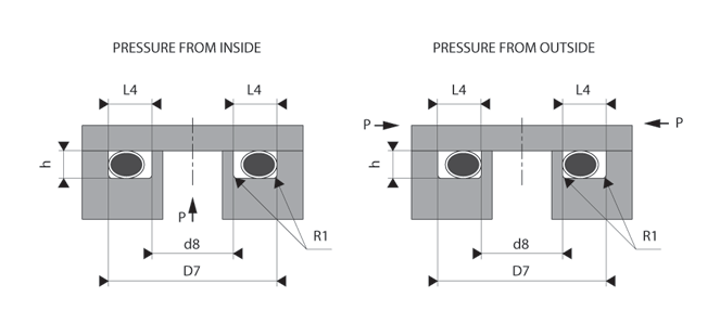
The table below sets out the design recommendations for axial sealing.
| Axial sealing | ||||
|---|---|---|---|---|
| Cross-section Ød2 | h | Tolerance ± | L4 | Tolerance ± |
| 1,60 | 1,20 | 0,02 | 2,50 | 0,20 |
| 1,78 | 1,30 | 0,02 | 2,70 | 0,20 |
| 2,00 | 1,40 | 0,02 | 3,00 | 0,20 |
| 2,50 | 1,83 | 0,03 | 3,50 | 0,20 |
| 2,62 | 1,96 | 0,03 | 3,75 | 0,20 |
| 3,00 | 2,25 | 0,05 | 4,15 | 0,20 |
| 3,15 | 2,55 | 0,05 | 4,60 | 0,20 |
| 3,53 | 2,65 | 0,05 | 4,95 | 0,20 |
| 4,00 | 3,05 | 0,05 | 5,25 | 0,20 |
| 4,30 | 3,25 | 0,05 | 5,50 | 0,20 |
| 4,50 | 3,45 | 0,05 | 5,80 | 0,20 |
| 5,00 | 3,85 | 0,05 | 6,40 | 0,20 |
| 5,33 | 4,30 | 0,05 | 7,25 | 0,20 |
| 5,50 | 4,38 | 0,05 | 7,30 | 0,20 |
| 5,70 | 4,45 | 0,05 | 7,40 | 0,20 |
| 6,00 | 4,85 | 0,05 | 7,80 | 0,20 |
| 6,30 | 5,20 | 0,05 | 8,20 | 0,20 |
| 6,99 | 5,75 | 0,05 | 9,10 | 0,20 |
| 8,00 | 6,40 | 0,07 | 10,20 | 0,20 |
| 8,40 | 6,65 | 0,07 | 10,90 | 0,20 |
| 9,00 | 7,30 | 0,07 | 11,70 | 0,20 |
| 9,50 | 7,80 | 0,10 | 12,30 | 0,20 |
| 10,00 | 8,20 | 0,10 | 13,00 | 0,20 |
| 11,00 | 9,20 | 0,10 | 14,30 | 0,20 |
| 12,00 | 10,00 | 0,10 | 15,60 | 0,20 |
To make the tubes and rods, we recommend using non-porous steel or cast iron. For dynamic applications, brass and untreated stainless steel, as well as aluminium, are not as hard and are therefore not recommended, as they would be subjected to a lot of wear.
The roughness means that the sealing must be of a high quality. The surface roughness of grooves improves during alternating pressures.
| Type of application | Type of surface | Roughness Ra |
Roughness Rz |
Roughness Rmax |
|---|---|---|---|---|
| Radial - Static | Under non-pulsating pressure | |||
| Mating surface (rod and cylinder) | 1,6 µm | 6,3 µm | 10,0 µm | |
| Groove diameter and groove flanks | 1,6 µm | 6,3 µm | 10,0 µm | |
| Under pulsating pressure | ||||
| Mating surface (rod and cylinder) | 0,8 µm | 3,2 µm | 5,0 µm | |
| Groove diameter and groove flanks | 1,6 µm | 6,3 µm | 10,0 µm | |
| Axial - Static | Clamping surface | 1,6 µm | 6,3 µm | 10,0 µm |
| Groove flanks | 1,6 µm | 6,3 µm | 10,0 µm | |
Given that the O'Rings are fitted pre-tightened, the chamfer lengths and rounded cutting edges must fit with the table below.
| Cross-section Ød2 |
Radius R1 |
Max radius R2 |
Chamfer C |
|
|---|---|---|---|---|
| 15° | 20° | |||
| 1,78 - 1,80 | 0,30 | 0,20 | 2,50 | 2,00 |
| 2,62 - 2,65 | 0,30 | 0,20 | 3,00 | 2,50 |
| 3,53 - 3,55 | 0,60 | 0,20 | 3,50 | 3,00 |
| 5,33 - 5,30 | 0,60 | 0,20 | 4,00 | 3,50 |
| 6,99 - 7,00 | 1,00 | 0,20 | 5,00 | 4,00 |
| 8,40 | 1,00 | 0,20 | 6,00 | 4,50 |
Only on request