BECA 806


Description
The BECA 806 profile is a shaft seal composed of a primary sealing lip with filled PTFE pumping leads; one section can be made of felt, preventing depression in the area, and a coating with rubber grooves.
Advantages
Excellent chemical inertia
Very good friction coefficient; no stick-slip effect
Optimised static sealing
Technical data
| Temperature | -60°C/+200°C |
|---|---|
| Pressure | 0.50 MPa |
| Speed | 50 m/s |
Applications
Motors
Crankshafts
Materials
Rubber
ACM 70 - 75 Shore A
FKM 70 - 75 Shore A
HNBR 70 - 75 Shore A
NBR 70 - 75 Shore A
Sealing lip
Virgin PTFE
Glass-filled PTFE
Carbon-filled PTFE
Metal cage
Steel - AISI 1010
Stainless steel - AISI 304
Stainless steel - AISI 316
Deflector
Felt (optional)
for use
Dimensions

Materials
Metal cage
The table below shows the materials that we can offer for metal cages.
| Application | Material | Standard | Characteristics |
|---|---|---|---|
| Metal cage | Non-alloy standard steel | AISI 1010 (DIN 1624) |
Cold rolled steel |
| Metal cage | Nickel chrome steel | AISI 304 (DIN 1.4301 - V2A) |
Standard stainless steel |
| Metal cage | Chrome-nickel-molybdenum steel | AISI 316 (DIN 1.4401 - V4A) |
Stainless steel highly resistant to corrosion |
PTFE
PTFE is a thermoplastic polymer made of tetrafluoroethylene with exceptional properties - very low friction coefficient (adhesive friction and sliding friction are almost equal), physiologically safe for temperatures up to +200°C, excellent electrical insulation properties, and excellent chemical compatibility with the majority of fluids. On the other hand, as this material is plastic and not elastic, so it cannot easily replace rubber bases.
NBR (Nitrile Butadiene Rubber)
Nitrile rubber (NBR) is the general term for acrylonitrile-butadiene copolymer. The ACN content can vary between 18% and 50%. While the acrylonitrile content is important, the resistance to oil and fuel is more so. Conversely, the elasticity and compression set are not as good. The NBR has good mechanical properties and good wear resistance. However, its resistance to atmospheric agents and the ozone is relatively low.
| Chemical resistance | Aliphatic hydrocarbons (propane, butane, petroleum, diesel fuel) Mineral oils and greases Fire-resistant fluids (HFA, HFB and HFC) Diluted acids, low-temperature alkaline and saline solutions Water (up to +100°C max) |
|---|---|
| Compatibility issue | Fuels with high aromatic content Aromatic hydrocarbons (benzene) Chlorinated hydrocarbons (trichlorethylene) Polar solvents (ketone, acetone, acetic acid, ethylene-ester) Strong acids Glycol-based brake fluids Atmospheric and ozone agents |
| Temperature range | -30°C / +100°C (short-term peak at +120°C) -40°C / +100°C with particular NBRs |
FKM (fluorinated rubber)
Depending on their structure and fluorine content, the chemical resistance and resistance to the cold in fluororubbers can vary. This FKM-based rubber is very often used for high-temperature hydraulics and pneumatics, for industrial valves, injection/fuel systems, motor seals and high-vacuum systems.
| Chemical resistance | Mineral oils and greases, ASTM n°1, IRM 902 and IRM 903 oils. Fire-resistant liquids (HFD) Silicone oils and greases Mineral and vegetable oils and greases Aliphatic hydrocarbons (propane, butane, petroleum) Aromatic hydrocarbons (benzene, toluene) Chlorinated hydrocarbons (trichlorethylene) Fuel (including high alcohol content) Atmospheric and ozone agents |
|---|---|
| Compatibility issue | Glycol-based brake fluids Ammonia gas Organic acids with a low molecular weight (formic and acetic acids) |
| Temperature range | -20°C / +200°C (short-term peak at +230°C) -40°C / +200°C with particular FKMs |
Conditions for use
Speed
The table below indicates the relationships between the linear speed, the rotation speed and the recommended material.
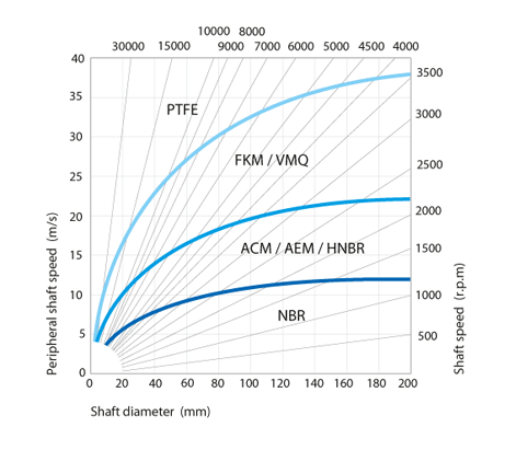
Linear speed calculation:
s (m/s) = [Ø shaft (mm) x speed (rpm) x π] / 60,000
The linear speed cannot exceed 50 m/s.
Temperature
The table below indicates the temperature limits depending on the PTFE and fluids used.
| Media | Maximum temperature depending on the materials | |
|---|---|---|
| PTFE | ||
| Mineral oils | Oils for motors | +150°C |
| Oils for gearboxes | +150°C | |
| Oils for hypoid gears | +150°C | |
| ATF oils | +150°C | |
| Hydraulic oils | +150°C | |
| Greases | +150°C | |
| Fire-resistant fluids |
HFA group - Emulsion with more than 80% water | + |
| HFB group - Opposite solution (water in oil) | + | |
| HFC group - Polymer aqueous solution | + | |
| HFD group - Water-free synthetic fluids | +150°C | |
| Other fluids | EL + L heating oil | + |
| Air | +150°C | |
| Water | + | |
| Water for washing | + | |
| Temperature range | Min. | -60°C |
| Max. | +200°C | |
+: resistant but not commonly used with these fluids
Fluids
Mineral oils
In general, this type of oil has few additives and is therefore perfectly suitable for all of the rubbers used for the rotary shaft seals. The following oils are suitable for revolving applications:
- motor oils
- gearbox oils
- hypoid oils
- ATF oils for automatic gearboxes
- transmission oils
synthetic oils
This type of oil is used to improve different characteristics such as the resistance to ageing, resistance to high temperatures, viscosity, etc. and has a good compatibility with the majority of rubbers used for the seals for the rotary shaft. Tests may need to be performed beforehand to measure the degree of compatibility of this type of oil with the materials used. Among the synthetic oils are:
- brake fluids
- fluids for automatic gearboxes
- fluids for suspensions
- fluids for steering systems
- fluids for hydraulic transmissions
Hypoid oils
This type of oil contains special components such as EP additives. These enable lubrication and thus limit any seizing at the bearings, for example. When affected by heat, these additives have the tendency to lead to deposits on the sealing lip. That is why we recommend using seals for the rotating shaft with a sealing lip comprising return pumping leads in order to limit the increase in temperature and above all, to reduce these potential carbon deposits.
Greases
Greases are generally applied to bearings etc. and require specific adaptation to provide favourable operating conditions for the rotary shaft seal. To prevent the lip of the seal from sustaining more significant pressures than planned, we recommend positioning the lip seal on one side of the bearing in such a way so that the lip is not prematurely destroyed. We also recommend reducing the rotation speed by 50% when lubricated, to ensure that less heat escapes during friction.
Aggressive fluids
It is critical to choose the correct material to better resist different aggressive fluids (acids, solvents, chemical products, etc.). For applications in a rotating environment, we recommend using materials such as FKM rather than NBR. For operations that are dry or use very little lubrication, and where the rubbers do not resist certain aggressive fluids, we advise you to use our PTFE seals for the rotary shaft.
Seal design
Tolerance for the outside diameter of the seal (ØD)
The table below indicates the pre-tightening for shaft seals on the housing diameter according to standard ISO 6194-1.
| Bore diameter ØD1 (mm) |
Tolerances on the outside diameter ØD of the ring | Roundness tolerance | |||
|---|---|---|---|---|---|
| Apparent metal cage | Rubber coating | Coating with grooves | Apparent metal cage | Rubber coating | |
| ØD1 ≤ 50.0 | +0.10 / +0.20 | +0.15 / +0.30 | +0.20 / +0.40 | 0.18 | 0.25 |
| 50.0 < ØD1 ≤ 80.0 | +0.13 / +0.23 | +0.20 / +0.35 | +0.25 / +0.45 | 0.25 | 0.35 |
| 80.0 < ØD1 ≤ 120.0 | +0.15 / +0.25 | +0.20 / +0.35 | +0.25 / +0.45 | 0.30 | 0.50 |
| 120.0 < ØD1 ≤ 180.0 | +0.18 / +0.28 | +0.25 / +0.45 | +0.30 / +0.55 | 0.40 | 0.65 |
| 180.0 < ØD1 ≤ 300.0 | +0.20 / +0.30 | +0.25 / +0.45 | +0.30 / +0.55 | 0.25% of ØD | 0.80 |
| 300.0 < ØD1 ≤ 500.0 | +0.23 / +0.35 | +0.30 / +0.55 | +0.35 / +0.65 | 0.25% of ØD | 1.00 |
| 500.0 < ØD1 ≤ 630.0 | +0.23 / +0.35 | +0.35 / +0.65 | +0.40 / +0.75 | - | - |
| 630.0 < ØD1 ≤ 800.0 | +0.28 / +0.43 | +0.40 / +0.75 | +0.45 / +0.85 | - | - |
Shaft design
Shaft material
Suitable materials are:
- ordinary C35 and C45 steels used in mechanical construction
- 1.4300 and 1.4112 stainless steels for sealing water
- sprayed carbide coatings
- graphite
- malleable cast iron
- materials with a CVD and PVD coating
Not appropriate:
- chrome coatings solidified through non-uniform wear
- plastic materials resulting from low thermal conductivity, which can lead to a disturbance in the transport of heat, an increase in temperature in friction areas with the shaft seal, as well as a potential softening
Shaft hardness
Shaft hardness will depend on the linear speed (in m/s) and the level of pollution.
| Rotation speed | Hardness in HRC |
|---|---|
| s ≤ 4.0 m/s | 45 HRC |
| 4.0 < s ≤ 10.0 m/s | 55 HRC |
| s > 10.0 m/s | 60 HRC |
Surface roughness
The recommendations below must be considered for the quality of the shaft surface area.
Standard conditions:
- Ra = 0.1 to 0.4 µm
- Rz = 1.0 to 4.0 µm
- Rmax ≤ 6.3 µm
Shaft tolerance
The shaft must have a tolerance of h11, in line with standard ISO 286-2
| Shaft diameter Ød1 (mm) |
Tolerance h11 (mm) |
|---|---|
| Ød1 ≤ 3.0 | -0.060 / 0 |
| 3.0 < Ød1 ≤ 6.0 | -0.075 / 0 |
| 6.0 < Ød1 ≤ 10.0 | -0.090 / 0 |
| 10.0 < Ød1 ≤ 18.0 | -0.110 / 0 |
| 18.0 < Ød1 ≤ 30.0 | -0.130 / 0 |
| 30.0 < Ød1 ≤ 50.0 | -0.160 / 0 |
| 50.0 < Ød1 ≤ 80.0 | -0.190 / 0 |
| 80.0 < Ød1 ≤ 120.0 | -0.220 / 0 |
| 120.0 < Ød1 ≤ 180.0 | -0.250 / 0 |
| 180.0 < Ød1 ≤ 250.0 | -0.290 / 0 |
| 250.0 < Ød1 ≤ 315.0 | -0.320 / 0 |
| 315.0 < Ød1 ≤ 400.0 | -0.360 / 0 |
| 400.0 < Ød1 ≤ 500.0 | -0.400 / 0 |
Chamfer and radius
You are strongly advised to install a chamfer on the shaft so as not to alter the primary sealing sealing lip of the shaft seal during assembly. Please refer to the table below.
| Shaft diameter Ød1 (mm) |
Chamfer diameter Ød3 (mm) |
Radius R (mm) |
|---|---|---|
| Ød1 ≤ 10.0 | Ød1 - 1.50 | 2.00 |
| 10.0 < Ød1 ≤ 20.0 | Ød1 - 2.00 | 2.00 |
| 20.0 < Ød1 ≤ 30.0 | Ød1 - 2.50 | 3.00 |
| 30.0 < Ød1 ≤ 40.0 | Ød1 - 3.00 | 3.00 |
| 40.0 < Ød1 ≤ 50.0 | Ød1 - 3.50 | 4.00 |
| 50.0 < Ød1 ≤ 70.0 | Ød1 - 4.00 | 4.00 |
| 70.0 < Ød1 ≤ 95.0 | Ød1 - 4.50 | 5.00 |
| 95.0 < Ød1 ≤ 130.0 | Ød1 - 5.50 | 6.00 |
| 130.0 < Ød1 ≤ 240.0 | Ød1 - 7.00 | 8.00 |
| 240.0 < Ød1 ≤ 500.0 | Ød1 - 11.00 | 12.00 |
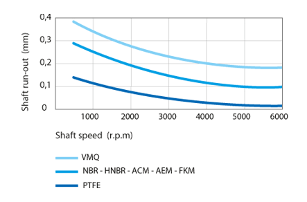
Shaft run out
The shaft run out is a deviation between the current shaft axis and the theoretical rotation axis. It is important to reduce the shaft run out as much as possible by positioning the shaft seal as close as possible to the bearing. The table below sets out the maximum permissible values depending on the rotation speed and the sealing lip material.
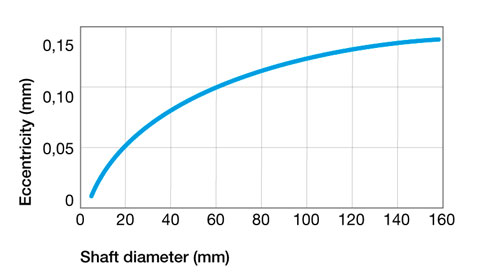
Eccentricity
The shaft and housing must be assembled centred on one another in order to remove any unilateral radial load at the sealing lip of the ring.
Shaft machining
Correct shaft machining is essential to the proper operation of the sealing system.
- Plunge grinding: preferred machining method that ensures the absence of striations on the shaft (0 +/- 0.05°)
- Turning: suitable for shafts used with a unidirectional sense of rotation
Machining guidelines for surface adjustments
| Parameters | Requirements |
|---|---|
| Speed of the part to be machined | 30 to 300 rpm |
| Wheel speed | 1500 to 1700 rpm |
| Surfacing feed | < 0.02 mm/turn |
| Dressing tool | multi-grain dressing diamond, single drain dressing diamond |
| Grinding rate feed | approximately 0.02 mm |
| Spark duration | full spark, min. 30 secs |
| Passing depth | > Rmax of the old machining operation |
| Eccentricity of the tool and part to be machined | the best possible |
Housing design
Surface roughness
The recommendations below must be considered for the quality of the housing surface area.
Standard conditions for rings with a rubber coating:
- Ra = 1.6 to 6.3 µm
- Rz = 10.0 to 25.0 µm
- Rmax ≤ 25.0 µm
Tolerance of the bore diameter of the housing
The bore diameter of the housing must have a tolerance of H8, in line with standard ISO 286-2
| Bore diameter ØD1 (mm) |
Tolerance H8 (mm) |
|---|---|
| 3.0 < ØD1 ≤ 6.0 | 0 / +0.018 |
| 6.0 < ØD1 ≤ 10.0 | 0 / +0.022 |
| 10.0 < ØD1 ≤ 18.0 | 0 / +0.027 |
| 18.0 < ØD1 ≤ 30.0 | 0 / +0.033 |
| 30.0 < ØD1 ≤ 50.0 | 0 / +0.039 |
| 50.0 < ØD1 ≤ 80.0 | 0 / +0.046 |
| 80.0 < ØD1 ≤ 120.0 | 0 / +0.054 |
| 120.0 < ØD1 ≤ 180.0 | 0 / +0.063 |
| 180.0 < ØD1 ≤ 250.0 | 0 / +0.072 |
| 250.0 < ØD1 ≤ 315.0 | 0 / +0.081 |
| 315.0 < ØD1 ≤ 400.0 | 0 / +0.089 |
| 400.0 < ØD1 ≤ 500.0 | 0 / +0.097 |
| 500.0 < ØD1 ≤ 630.0 | 0 / +0.110 |
Groove width
The table below provides information on the recommended groove width.
| Height H1 (mm) |
Width | |
|---|---|---|
| L2 min (mm) | L1 min (mm) | |
| 7.00 | 5.95 | 7.50 |
| 8.00 | 6.80 | 8.50 |
| 10.00 | 8.50 | 11.00 |
| 12.00 | 10.30 | 13.00 |
| 15.00 | 12.75 | 16.00 |
| 20.00 | 17.00 | 21.00 |
Groove radius
The table below provides information on the recommended radius.
| Height H1 (mm) |
Radius R2 max (mm) |
|---|---|
| 7.00 | 0.50 |
| 8.00 | |
| 10.00 | |
| 12.00 | 0.70 |
| 15.00 | |
| 20.00 |
Only on request